Department Events
Conduction of the “Department Advisory Board Meeting”
The
department conducted the “Department
Advisory Board Meeting” with Dr. P.
B. Darji, Associate Professor, SVNIT Surat, Dr. Ujval Sonone, Sr. Manager-Technology Center-AIS, ABB India
Limited, Nashik, Shri. Pramod Haribhau
Abhang, Assistant Vice President, Popular Switchgears Private Limited,
Nashik, and all the faculty and staff members of the department. This meeting
was conducted for discussing the vision, mission, PEOs, PSOs, and the Strategic
Plan of the Department. The members provided important suggestions and inputs
on all the points.


Expert lecture on Introduction to IoT 4.0
An Expert lecture was arranged in association with the IEEE Students Chapter of the Electrical department on “Introduction to IoT 4.0” for F.Y. B.Tech (N-Div) students and staff members on 13/01/2023. The resource person was Mr. Rahul Mane, Manager, Digital Solution, Motwane Manufacturing Company Pvt. Ltd. Total No. of Students present in the session was 44. This lecture helped students to acquire knowledge application of latest trends measuring instruments.

Student Corner
Student Placement
The following
students are placed in various multinational companies in January 2023 Congratulations
to all the students!
|
Sr. No. |
Name of the Student |
Placement Date |
Batch |
|
1. |
Dhanashri Bhagawant sonawane |
03/01/2023 |
2022-23 |
|
2. |
Jayesh Raju Gulale |
03/01/2023 |
2022-23 |
|
3. |
Kunjan sanjay patil |
03/01/2023 |
2022-23 |
|
4. |
Shivanshu Pramod Bari |
03/01/2023 |
2022-23 |
|
5. |
Tanmay Santosh Patil |
03/01/2023 |
2022-23 |
|
6. |
Vaibhav
Gajanan Dhanokar |
03/01/2023 |
2022-23 |
|
7. |
Nikhil Sunil Aware |
03/01/2023 |
2022-23 |
|
8. |
Omkar Sanjay Bhange |
03/01/2023 |
2022-23 |
|
9. |
Siddhant Milind Shegaonkar |
03/01/2023 |
2022-23 |
|
10. |
Somesh Sanjay Bhosale |
03/01/2023 |
2022-23 |
|
11. |
Srushti Kiran Pawar |
03/01/2023 |
2022-23 |
|
12. |
Rushikesh Sanjay Borse |
24/01/2023 |
2022-23 |
|
13. |
Sakshi Vilas Lokhande |
24/01/2023 |
2022-23 |
|
14. |
Abhishek
Devendra Shirsole |
24/01/2023 |
2022-23 |


Project presentation organized
by Internal Quality Assurance Cell (IQAC)
Presentation of the two top scorer project groups of the
Department was arranged at the Internal Quality Assurance Cell (IQAC) of the
institute on 31/01/2023. One group is guided by Dr. R. K. Munje and the other by Prof. G. N. Jadhav. Project monitoring is done by Project
Coordinators, Dr. S. S. Dhamal and Prof. A. M. Shewale.

Visited GE Aviation, Pune for campus placement
Final year students visited “GE Aviation” Pune for campus placement on 25/01/2023 with Prof. Saravanan and Prof. Snehal Sagare. Wonderful
experience for all the students.

Congratulations
Electrical TE (A-Div) student, Rohit Rokade has
successfully completed the 16 hours of the Industry Connect program from
05/09/2021 to 17/10/2022.

The Indian Air Force has organized a special student interaction road drive for KK Wagh Students
The Indian Air Force has organized a special student
interaction road drive for K. K. Wagh students on 28th January 2023.
Highlights of interaction are as below:
(a) IAF Officials have interacted with students so that they
become aware of IAF.
(b) Guided various career opportunities available in the Air
Force Area
(c) Showcase of “Induction publicity exhibition vehicle”
(IPEV) developed specially by IAF This Air Force bus is similar to the Aircraft
Simulator and was demonstrated in the batch of 15 students and given the experience
of Aircraft. A total of 400 students participated. Event coordinators Prof P. B. Surwade and Prof. Saravanan S.

Faculty Corner
Industrial Training/Courses done by staff during January 2023
Prof. S. A Sagare and Prof. P. V. Dhole visited Advent Power
Tech Pvt.Ltd, on 5th January 2023, and interacted with Ms. Premlata
Mishra.
Prof. Ganesh N. Jadhav visited Indian Oil Corporation Ltd.
on 1st January 2023 and interacted with Mr. K. Gururaj.
Dr. R. K. Munje, Dr. S. S. Dhamal, Prof Nayana N Jangle,
Prof. S. K. Shinde, and Prof. A. M. Shewale visited Nashik Engineering Cluster
on 17th January 2023 and interacted with Mr. Manvendra Yadav, DGM
Innovation Incubation and Skill Development.
Dr. S. S. Dhamal and Prof. S. K. Shinde visited PVN
Transformer Pvt..Ltd. Ambad, on 19th January 2023 and interacted
with Mr. Parag Valmik Nikhade.
Dr. R. K. Munje, and Dr. S. S. Dhamal, visited Crompton
Craves Ltd. Nashik, on 16th January 2023 and interacted with Mr.John Yesuraj.
Faculty Publication
Ravindra Munje, Priya Rakibe, Vikrant Nichit, Anup Dudhekar, and Yogita Shewale. New Approach for Providing Adaptable Curriculum Enrichment through Teaching-Learning and Evaluation. Journal of Engineering Education Transformations (2023). Volume: 36, Issue: Special Issue 2, Pages: 425-430
School Innovation Council
Dr. R. K. Munje delivered a session on the
constitution of the School Innovation Council under the Ministry of Education's
Innovation Cell at the K. K. Wagh Universal School, Saraswati Nagar, Nashik on
10th January 2023.

Death Anniversary
Remembering Late Hon. Shri. Balasaheb Wagh on his Death
anniversary (26/01/2023).

Student Articles
Vacuum circuit breaker

Umesh
Namdev Kalyankar,
TE-Div B, (Electrical)
1. Introduction
A breaker that uses a vacuum as an arc extinction medium is
called a vacuum circuit breaker. In this circuit breaker,
the fixed and moving contacts are enclosed in a permanently sealed vacuum
interrupter. The arc is extinct as the contacts are separated in a high vacuum.
It is mainly used for medium voltage range, i.e. from 11 kV to 33 kV. The vacuum circuit breaker has
a high insulating medium for arc extinction as compared to the other circuit breaker. The pressure inside the
vacuum interrupter is approximately 10-4 torrent and at this
pressure, very few molecules are present in the interrupter. The vacuum circuit
breaker has mainly two phenomenal properties.
1) High insulating
strength: In comparison to various other insulating media used in circuit
breaker vacuum is a superior dielectric medium. It is better than all other
media except air and SF6, which are employed at high pressure.
2) When an arc is opened by moving
apart the contacts in a vacuum, an interruption occurs at the first current
zero. With the arc interruption, their dielectric strength increases up to a
rate of thousands of times as compared to other breakers.
The above two properties make the breakers more efficient, less bulky, and cheaper. Their service life is also much greater than any other circuit breaker, and almost no maintenance is required.
2. Construction
The internal view of this breaker is shown in Figure 1. (a) and (b), The circuit breaker consists of a molded insulator, housing three (3) vacuum interrupters and an operating mechanism that uses the spring stored energy system.


Figure1. (a). The circuit breaker consists of a molded insulator, b) vacuum interrupters, and an operating mechanism
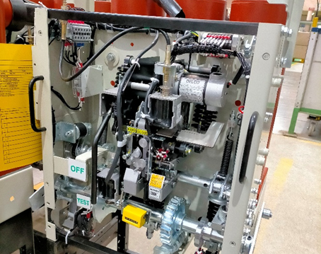
Figure 2. Energy Storing Mechanism
3.
Operations
The motor energy-storing mechanism of the breaker is shown in Figure 2.
i) Charging of Closing
spring
When the power supply is connected to the operation circuit, energy from the motor is stored in the closing spring. When the spring changing is complete, the limit switches cut the motor supply. The indicator turns from white to yellow CHARGED condition, corning that the spring charging is complete. As the closing spring may be released by a closing signal, the limit switch closes when the closing operation terminates, causing the motor to run.
ii) Closing operation
When the closing coil is excited by
a closing signal, the closing catch is released and the closing cam is rotated
by the closing spring, which in turn rotates the main shaft. The main shaft
drives the vacuum interrupters through the wipe spring, and the circuit breaker
closes.
iii) Tripping operation
When the tripping coil is excited
by a tripping signal, the tripping catch is released, and the breaker is opened
by the opening spring
4. Working Vacuum Circuit Breaker
When the
fault occurs in the system, the contacts of the breaker are moved apart and
hence the arc is developed between them. When the current-carrying contacts are
pulled apart, the temperature of their connecting parts is very high due to
which ionization occurs. Due to the ionization, the contact space is filled
with the vapor of positive ions which is discharged from the contact material.
The density of vapor depends on the current in the arcing. Due to the decreasing mode of the current wave their rate of release of vapor fall and after the current zero, the medium regains its dielectric strength providing vapor density around the contacts reduced. Hence, the arc does not restrike again because the metal vapor is quickly removed from the contact zone.
5. Advantages of VCB
Vacuum offers the utmost insulating strength. So, it has extremely superior arc quenching properties than any other medium.
The vacuum circuit breaker has a long life.
Unlike Oil Circuit Breaker (OCB)
or air blast Circuit Breaker (ABCB), the explosion of a VCB is avoided. This
enhances the safety of the operating personnel.
No fire hazard
The vacuum CB is fast in
operation so ideal for fault clearing. VCB is suitable for repeated operations.
Vacuum circuit breakers are
almost maintenance-free.
No exhaust of gas to the
atmosphere and Noiseless operation.
6. Disadvantages of VCB
The main disadvantage of
VCB is that it is uneconomical at voltages exceeding 38 kV.
The cost of the breaker
becomes excessive at higher voltages. This is because at high voltages (above
38 kV) more than two numbers of the circuit breaker are required to be
connected in series.
Moreover, VCB production is
uneconomical if produced in small quantities.
7. Applications of Vacuum Circuit Breaker
The vacuum circuit breaker is today recognized as the most reliable current interruption technology for medium voltage switchgear. It requires minimum maintenance compared to other circuit breaker technologies. The technology is mainly suitable for the mainly medium-voltage application. Higher voltage vacuum technology has been developed, but it is not commercially feasible. Vacuum circuit breakers are used in metal-clad Switchgear and also in porcelain-housed circuit breakers.
Power Transformer

Roshan
Ramesh Bodke TE-Div B, (Electrical)
Bodkeroshan632@gmail.com
1.
What are Power Transformers?
A
power transformer is a mere classification of transformers with a voltage range
varying between 33 kV-400 kV and a rating above 200 MVA. The voltage ratings of
power transformers available in the market include 400 kV, 200 kV, 110 kV, 66
kV, and 33 kV. The other types of transformers include distribution (230 V-1kV)
and instrument transformers.
2. Common Types of Transformer Protection
Faraday’s
Law of Electromagnetic Induction
Faraday’s
law states that when a closed loop is brought near a fluctuating magnetic
field, an electromotive force (emf) will be induced across it.
Power
transformers are electrical instruments used in transmitting electrical power
from one circuit to another without changing the frequency. They operate by the
principle of electromagnetic induction. They are used in transmitting
electrical power between generators and distribution primary circuits. Power
transformers are used to step up or step down the voltage in distribution
networks. Since they have no rotating or moving parts, these instruments are
considered static devices. These instruments work based on an alternating
current (AC) electrical system.
Overheating protection
Overcurrent protection
Differential Protection of Transformer
Earth Fault Protection (Restricted)
Buchholz (Gas Detection) Relay
Over-fluxing protection
Operating Principle of Power Transformers
The efficiency of the power transformer has very
high and works at its full efficiency.
AC passes through the primary winding, which creates a
varying magnetic flux.
The magnetic field that results strikes the second winding and generates an AC voltage in that winding via electromagnetic induction

Figure.1. Transformer Working Principle
3. Stepping Voltages Up or Down
The total voltage in a winding is equal to the voltage
per turn of the coil multiplied by the number of turns. Since the voltage per
turn of the primary and secondary windings are the same, the induced voltage in
the secondary winding can be related to the input voltage on the primary
winding.
This relationship is expressed by the equation:
Vs = Vp/Np x Ns
Where V represents the total voltage in the winding, N
represents the number of turns of a winding, and the subscripts p and s refer
to the primary and secondary windings, respectively. The ratio of the number of
turns in the secondary winding to that of the primary winding (Ns/Np) is called
the turns ratio. If the number of turns in the secondary winding is fewer than
the number of turns in the primary winding, the voltage output is lower than
the input voltage (step-down transformer). On the other hand, if the number of
turns in the secondary winding is more than the number of turns in the primary
winding, the voltage output is higher than the input voltage (step-up
transformer). Since energy is conserved, the relationship between the
alternating current in the primary and secondary windings is represented by the
below equation:
Vp Ip = Vs Is
where I
represents the current.
Ratio of transformer:
N2/N1=V2/V1=I1/I2
Grounding use in power transformer:
Grounding transformers are typically used to provide a
relatively low-impedance path to the ground, thereby maintaining the system
neutral at or near ground potential. Limit the magnitude of transient overvoltages
when restriking ground faults occur. Provide a source of ground fault current
during line-to-ground faults. This is Reactor grounding.
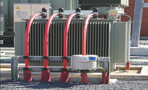
Figure.2. Transformer Working Model
3.1.
Transformer Losses
Copper Loss
Copper
losses, sometimes called resistive or I2R losses, are the energy losses caused
by the electrical resistance of the windings to current flow. The electrical
resistance of material measures the opposition to the current flow; it depends
on the length, nature, cross-sectional area, and temperature of the material.
Copper losses are also influenced by the amount of current flowing through the
circuit. Copper losses are quantified by calculating the value of I2R.
Hysteresis Loss
Hysteresis
losses are caused by the friction encountered by the ferromagnetic molecules in
the core due to magnetization and demagnetization, as the magnetizing force
flows in forward and reverse directions. The internal friction developed caused
heat to develop within the transformer.
Eddy Current Loss
Eddy
current is produced in the core’s cross-section as a result of the fluctuating
magnetic field. It is minimized by laminating thin metal sheets (laminas)
together to construct the transformer core. The laminas are insulated by a
special coating. Through lamination, the eddy current is produced and flows
separately in all laminas, and the path for the eddy current is drastically
reduced.

4. Summary
Power transformers are static electrical
instruments used in transmitting electrical power from one circuit to another
without varying the frequency. They have a voltage range varying between
33kV-400kV.
The principle behind the design and operation of
power transformers is based on Faraday’s law of electromagnetic induction.
The main components of power transformers are
primary winding, secondary winding, and core. The relationship between the
voltage and number of turns in the primary and secondary windings are related
by the equation: Vs = Vp/Np x Ns. This relationship is used in stepping up or
down voltages.
The other components of power transformers include
insulating materials, tap changers, bushings, transformer tanks, conservators,
breathers, cooling systems, explosion vents, and Buchholz relays.
Power transformers can be classified based on core
and winding construction, turn ratio, phases, and core material.


No comments:
Post a Comment